of junk. The projection system includes a Reciprocator, which could
have been a powerful sub-woofer or the "voice coil" of the head of
a Very old hard drive, since these may be able to reciprocate by
more than an inch. For a Reciprocator, we used a Lawnmower
engine driven in reverse by an electric motor.
The other part of the projection system was meant to be a pair
of parabolic mirrors which would carry the image from a reciprocating
surface into mid-air where it would safely appear.
BUT THAT DID NOT WORK VERY WELL.
Also, those mirrors were very large. Although our reciprocating
mechanism IS very large, as I have said, it does not need to be.
We found that an anomalous lens worked Very Well, and although
we could not find another, better lens, in our junk collection, we
know a little bit about the lens and a little bit about how it can
be improved. But for demonstration, it Works Very Well.
I recall seeing in a textbook a drawing representing how
lenses refract light. It showed a convex lens acting as a
magnifying glass. Concave lenses are often used as collimators
or reducing lenses, but in this diagram that I remembered,
something else was shown: Projection of an image on the
same side of the lens.

So the lens in the reciprocating part of the projector is a
concave lens. It may appear to be working as a mirror, but
quite anomalously, coating it on either side with reflective metal
made the image disappear, as also did, coating the back of the
lens with black material! Therefore, the concave lens is NOT
reflecting. Also noticed is that the apparent size of the virtual
image is not changed very much in the case of the lens, but
is changed greatly when mirrors are used.
(note: change 5/8/2004: the lens used is not a Double Concave
but has a convex side, for it is a common eyeglass lens.)
The other part of the projection system is a bright, high-speed,
static display. In our prototype, LEDs parallelly connected to an
array of latches (74HC574) was used. It is necessary that the
display does not Raster because the image would be very dim,
having been reduced by the inverse cube of the distance between
the voxel and the emitter. Digital Light Processors are an excellent
substitute for LEDs, because they handle very bright light and are
driven by static memory (and therefore present a Parallel image,
unlike a CRT raster). It is very tedious to build a high resolution
static LED display, or even the one we used. But latched LEDs are
able to be modulated at about 1MHz which is sufficient for producing
high resolution 3D images.
Update: Perhaps a type of cold cathode latching neon fluorescent
display would be effective as an image source. It has been known
since 1970 at least that cold cathode tubes turn on at a higher voltage
than they stay on, and that gives them a useful memory for massively
parallel display output. This is better than the first idea of using latched
LEDs.
This is a simplified design of the open air holograph we have invented:

The position of the sync trigger sensor is important, because it
determines where the image will appear. Moving the sensor vertically
will move the image vertically , even down into the reciprocating
lens. It is most effective to have the image project as far away from
the lens as possible. In this particular design, it is also important for
the processor to know whether the lens is moving up or down,
to prevent a mirror image from being generated.
Color is possible, although our prototype produces just yellow
images. It may be able to produce red and green also. To produce
full color, either a RGB light source may be used, or more simply,
a white source with an RGB color wheel.
Images which we have generated for our prototype have been
computer generated. The simplest editor we can imagine for this
display is a light pen. There are a number of methods of detecting
the location of a light pen in this display field, such as...
First determining the vertical position of the light pen and then
doing a quick raster across the plane of the active light source.
This is a picture of our prototype, uncovered. With the cover on,
the concave lens does not exit the hole in the cover, but the
projected image apparently does. The active light source protrudes
out of the box and is suspended above the reciprocating lens.
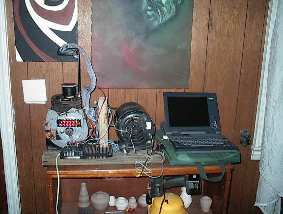
The reciprocator position is sensed by an open optocoupler beam-break,
which interrupts the processor which begins to feed image data into
the latched buffers, which are connected to the LEDs by the ribbon cables..
Another method that can be used to sense the reciprocator position is
a small rare-earth magnet and a tape head.
The processor is also interupted when serial data is fed to it.
The data is almost immediately stored in memory according to a
few different commands which describe what to do with it.
Commands:
ANIMATE: (## are hex frame numbers, 00 means repeat, FF means stop.)
a-## ## ## ## ## ## ...
FRAME SELECT: display and prepare to load optional data into a cubical bitmap bank. Prototype has 62 cubical frame banks.
f-##
If the prototype boots up and has no data, it loads an
animated demo image of a rotating nut inside of a cube from ROM.
Data is received from the RS-232 port at 19200 baud, 115200 is
also possible but not implemented.
Other commands are planned but not implemented:
DRAW LINE X1 Y1 Z1 X2 Y2 Z2 COLOR
UPLOAD
POINTSET X1 Y1 Z1 COLOR
DRAW SHAPE "UDLRFB"
AUTOROTATE
AUTOSCROLL
These commands would allow the device to operate without a
computer. The functions can already be done with one.
A "draw line" function must count along the axis with the
most distance. Otherwise, a dotted line would be drawn.
At worst, a divide by zero would happen if a vertical line
were to be drawn on the vertical axis. The shorter coordinates
for each dot are calculated by the same proportion of movement
between beginning and end as the long axis. This is how it is
done in 2 dimensions and also works in 3 dimensions.
This emulates VECTOR GRAPHICS in the 3D bitmap.
Rotation involves calculating the distance between points and
the axis of rotation, and also calculating and changing the current
angular position of each point. Since the prototype only does
integer math, if any, then the rotation calculations should be
done on a computer. The prototype can apparently rotate images without
the computer because the angular views are already rendered
and stored in the device's cubical bitmap frame banks.
Scrolling is simply shifting the voxels all in the same direction.
This is a deconstructed (simulated) view of our scrolling demo.
On the device, only part of the landscape can be seen, but
the plane does move as the landscape scrolls under it.

The final note on this device...
(precisely what Lens we used)
will appear soon (now).
We believe it is an uncut optometrist's stock
"DIOPTER NUMBER 8", which has a net concavity.
Since we only had one eye glass lens it is very likely that
experimentation with other eyeglass lenses the effect may
be improvable and certainly increased in scale.
An online video of this CUBE 3 "holodeck" prototype
in operation may be forthcoming, when it is uploaded into
new server space, as well as pictures of CUBE 1 and 2.
Old video demo: MPEG 30MB or Windows Media 600K
A design for CUBE 4 is set, which is a small prototype
for "holodeck" games and rooms. This design departs from
the technology of 2 and 3. We have very much experience
with 3D experimentation, and if CUBE 4 works, CUBE 5
may use the same technology on a larger scale and come
very close to meeting the expectations of those who have seen
the technology only in science fiction.
New:due to a disagreement between myself and a manufacturer
of a critical cube 4 part, I may not prototype it, but release the
design anyway...with strong implications not to use that part
but something else instead.
Other 3D projects may also be described on these pages soon.
I hope the simplicity of this project, which could have been done
as well in the 1980's, has not gone unnoticed.
Let's build the brighter future!
With a 47% share, homebrew technology is the leading VR platform!
(c)William Como, 2003 ; all rights reserved.
NEXT: PART 3: Holodeck Rooms