The short answer:
3D displays do not need any (or very much) code
any more than tube radios and TV's do!
I am working on it. This has to be simple because
(otherwise) you believe it can not be done. AND so
someone won't convince you that you need their
special expensive junk to run it.
stay tuned! [to be cleaned up]
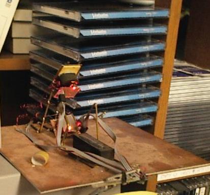
Here is a diagram of a possible cube5 holoemitter matrix element.
(Matrix=grid or memory mapped array)
It is a gimbaled optic, in this case a mirror, controlled by
electromagnets, and based on a previous design which used
two mirrors. This design is experimental and considered too
complicated to mass produce on a panel with consistency.
The estimated size would be 3 to 5 millimeters.

The mirror (in this case), or holographic optic (or fresnel lens),
is free to point in many directions. Without power, it is held
in flat alignment with it's neighbors by a plane of stationary
magnets identically positioned under the ones on the mirror itself.
Applying current to a field coil causes the mirror to move
predictably (so that if a laser was aimed at the mirror it would
reflect the beam as if it were the needle of a microammeter).
This design is based on combining two mirrors built to scan
laser beams into a line, into a single one that can scan in 2 dimensions.
As it is described now, it is possible to do all that a Cube 5
holoemitter can do, including sound (but not well). It would be
driven by a two MOSFET H-bridges, which would be able to
hold analog levels, and analog or PWM sound could be tapped in
(in a sort of makeshift way), but this whole element as described
is not simplified enough to be reasonably cheap and useful as a
Cube 5 element. Ignoring this, we consider a number of ways this
can be used...
A single one can do rough vector graphics (not relevant) or be used
with a strong laser to write on a wall (not relevant).
Assuming a wall was covered with these, and they were driven
according to the Beatty holographic method, red green and blue
strobes could colorize any holographic image displayed.
Another way of looking at what is going on here is, that it's possible
a room is continuously illuminated by red green and blue lamps, and
two of these mirrors could reflect the light from any one of the lamps
to each of your eyes, and you would then see a dot somewhere,
depending on which mirrors were activated. That method would
require way too many calculations and could not provide enough
dots. It could produce a full color image but only if you stood in
the right spot. Using the holographic method in the previous
paragraph makes the desired effect happen naturally without the
complexity and limitation just mentioned.
I have left out the complexity of addressing all of these things
since they are not certainly what I want to use. Also, using the
H-bridges analogly would vastly increase the power requirements.
Driving a cube-5 holoemitter matrix is like drawing a bunch of
arcs and circles on a normal monitor, except the appearance
is different. In the 3D display math board
page, there is (or will be) math enough for low-level graphing of circles,
and translating ZYX coordinates into holographic images of the same.
In most cases the 3D display function is a matter of counting through
the buffer memory and feeding it to the display mechanism. Here it
is seen to probably require translation; each active ZYX voxel will
cause concentric curves or circles to be added to the state of the
holomatrix. Empty voxels will be skipped if code is doing the conversion.
1/11/2004 to be continued
SIMPLER HOLOGRAPHIC ELEMENTS (? !)
These are very recent:
1.Magnetic Sequins
May be individually colored red green and blue!
Red parts are electromagnetic coils used to deflect
the sequin from it's natural vertical orientation toward light.

2.Macaroni Elements (not useful for sound)
Also useful for signs, these elements retain their state without power,
and may also have RGB colored ball bearings. This design assumes
that ball bearings can produce holographic effects. The red elements
are two coils that pull the BB from one side to the other. The BBs
are prevented from falling out by transparent sheets on each end.

1/12/2004